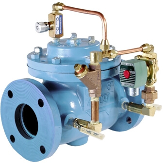
The OCV Series 115 Solenoid Control Valve is designed to provide on/off or open/close control of fluids in response to an electrical signal. The valve consists of the basic OCV model 65 with solenoid-operated pilot. With the appropriate solenoid, the valve may be normally closed (energize to open) or normally open (de-energize to open).
| Model | Model Sheet | Model Sheet (metric) | Specifications | Animation | Operations Manual |
|---|---|---|---|---|---|
| Model 115-1 Solenoid Shut-Off Valve |

|


|
|||
| Model 115-3 Solenoid Control Valve Throttling Type |

|


|
|||
| Model 115-4 Solenoid Control Valve High Capacity Type |

|


|
|||
| Model 115-26 Solenoid Shut-Off and Check Valve |

|
|

Used in irrigation and industrial processes, each flow line can be activated independently of others.
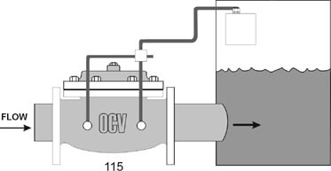
Valve, activated by level sensor, fills storage tank.
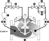
Operated by a 3-way solenoid. The main valve diaphragm chamber may be exhausted to atmosphere, allowing for full open operation at any flow rate. Standard with needle valve opening/closing speed control adjustment. Size ranges 1 ¼” – 4″, consult factory on application of larger sizes.
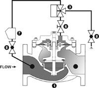
Operated by a 2-way solenoid and ejector. The main valve diaphragm is exhausted to valve outlet port. Valve position is determined by flow rate demand (differential pressure). Standard with needle valve opening/closing speed control adjustment. Size ranges 1 ¼” – 6″, consult factory on application of larger sizes.
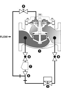
Operated by two 2-Way solenoids. The valve maybe positioned from full closed to full open or locked in any intermediate position. Equipped with both opening and closing speed adjustment. The valve can be configured to open, close, or hold position in the event of electrical power failure. The Model 115-3 is the basis for the OCV Series 22 Electronic Control Valves.
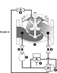
With Accelorator Operated by a 3-Way solenoid which operates a large port accelerator pilot, allowing quick response on larger valves. Standard valve includes needle valve opening/closing speed control adjustment. Size ranges 3 – 24″.
| Our ValveMaster selection and sizing software covers this in detail. However, if you do not have the software, sizing per the following procedure should result in satisfactory operation. | |
| 1. Decide whether a globe or angle valve will best fit your installation. Keep in mind that it is always best to install any control valve “bonnet up,” particularly in sizes 8″ and larger.
2. Begin with a line-sized valve. Calculate the pressure drop from the formula. |
|
| where:DP = pressure drop, psi sg = specific gravity of line fluid (water = 1.0) Q = rated flow of pump, gpm Cv = Valve coefficient from the table below. |
 |
| 3. The pressure drop calculated is that for a wide-open valve and would be true for an exhaust-to-atmosphere valve (115-1 or 115-4) regardless of flow rate. On the other hand, a valve exhausting to downstream (e.g., 115-2) may not be wide open. Refer to the “wide open at” column of the table. If the flow rate is less than this figure, the pressure drop of the valve can be 2-3 psi higher than the value calculated in Step 2. If the flow rate is higher than the figure given, the valves will be wide open and will have a pressure drop equal to the exhaust-to-atmosphere valve.
4. Check to see that the flow velocity does not exceed 20 ft/sec. If it does, or if the pressure drop is excessive, consider using the next size larger valve. 5. Finally, if an exhaust-to-atmosphere valve is selected, make note of the diaphragm chamber discharge. This quantity of water will be discharged to atmosphere each time the valve opens or closes. Provision should be made to drain or otherwise dispose of this water. |
|
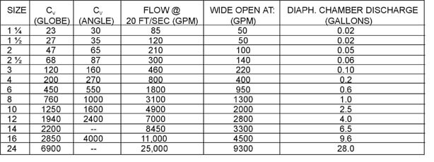
This chart shows only a sample of those most often specified valves. Consult the factory for specific data on the model you selected.
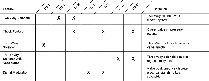
Combination valves can often reduce or eliminate other equipment. Example: If the system requires a reverse flow check function, the check feature can be added as a function of the Solenoid Valve Series 115.
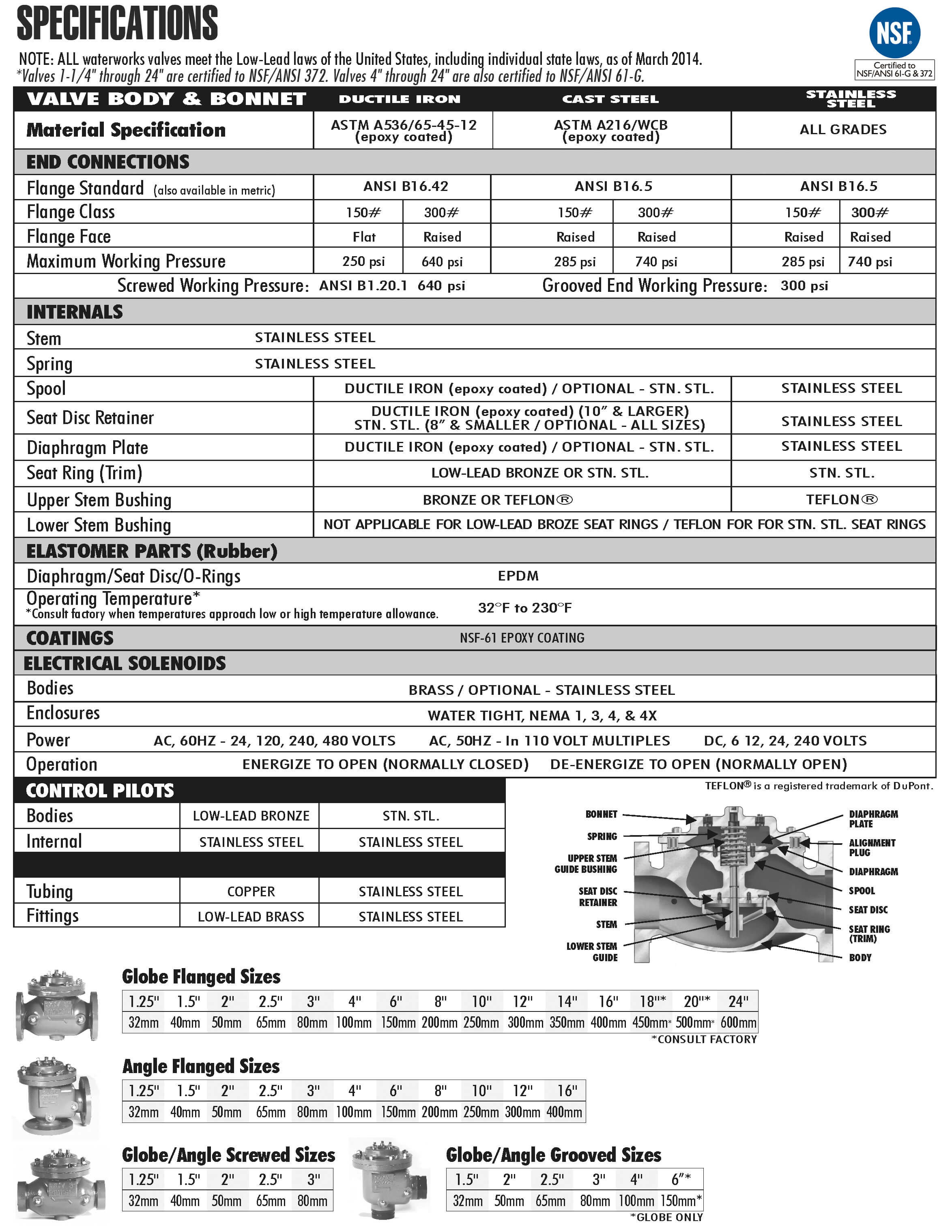
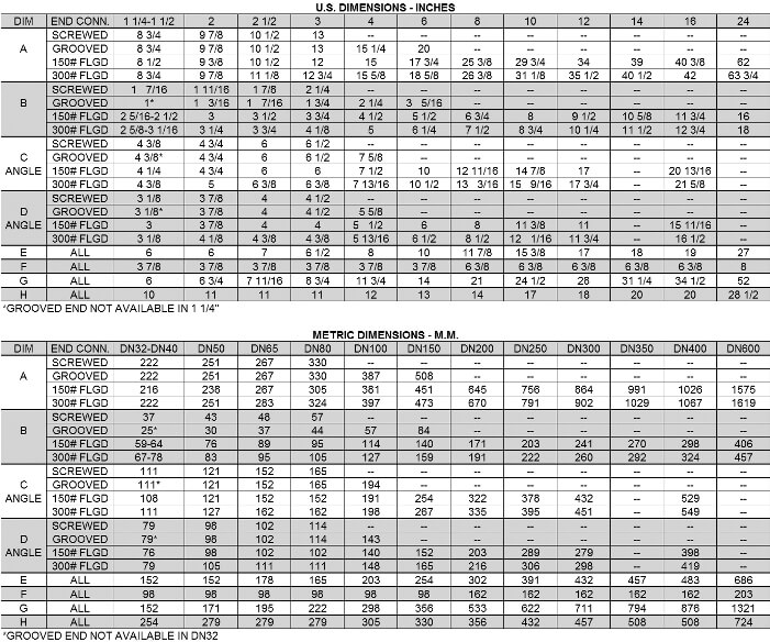
For maximum efficiency, the OCV control valve should be mounted in a piping system so that the valve bonnet (cover) is in the top position. Other positions are acceptable but may not allow the valve to function to its fullest and safest potential. In particular, please consult the factory before installing 8″ and larger valves, or any valves with a limit switch, in positions other than described. Space should be taken into consideration when mounting valves and their pilot systems.
A routine inspection & maintenance program should be established and conducted yearly by a qualified technician. Consult our factory @ 1-888-628-8258 for parts and service.

When Ordering please provide:
Series Number – Valve size – Globe or Angle – Pressure Class – Screwed, Flanged, Grooved – Trim Material – Adjustment Range – Pilot Options – Special needs / or installation requirements.